4. Logic Gates and Circuits
The functionality of even the most complex computer is achieved by connecting simple logic gates
into operational circuits.
Basic Gates
There are four basic logic gates. The symbols used for these gates and their "truth tables" are
given below (note that these are not the "standard" electrical engineering symbols for these gates).
- NOT : unary input; output is reverse of input

- AND : binary inputs: output is "on" only if both inputs are "on"

|
INPUTS |
OUTPUT |
|
Input-1 |
Input-2 |
|
0 |
0 |
0 |
| 0 |
1 |
0 |
| 1 |
0 |
0 |
| 1 |
1 |
1 |
- OR : binary inputs: output is "off" only if both inputs are "off"

|
INPUTS |
OUTPUT |
|
Input-1 |
Input-2 |
|
0 |
0 |
0 |
| 0 |
1 |
1 |
| 1 |
0 |
1 |
| 1 |
1 |
1 |
- XOR : binary inputs: output is "on" only if the inputs are different

|
INPUTS |
OUTPUT |
|
Input-1 |
Input-2 |
|
0 |
0 |
0 |
| 0 |
1 |
1 |
| 1 |
0 |
1 |
| 1 |
1 |
0 |
Basic Binary Encoding
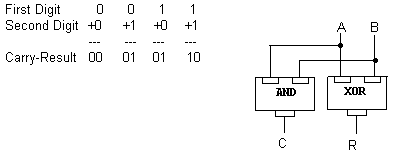
Basic Binary Addition
0+0 = 0
0+1 = 1
1+0 = 1
1+1 = 10 (i.e. the result in this "column" is 0 with a "carry" of 1 that needs to
be added to the next position to the left)
Logic Gate Application for Binary Addition

Truth Table for Single Bit Addition:
|
INPUTS |
OUTPUTS |
|
A |
B |
C |
R |
|
0 |
0 |
0 |
0 |
| 0 |
1 |
0 |
1 |
| 1 |
0 |
0 |
1 |
| 1 |
1 |
1 |
0 |
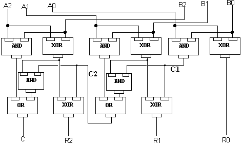
Addition of "words" with multiple "bits" extends this logic.

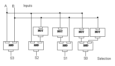
Selector
A collection of input wires or "bits" is "decoded" to turn on ("select") exactly one (output) circuit.
(This is contrary to Englander's definition in "The Architecture of Computer Hardware and
Software", page 720).

Multiplexor
A single input wire (at any one time) from a collection of possible inputs, is "encoded" into a
pattern on a smaller collection of wires. A multiplexor performs the reverse function of a
"selector". (The 2-input to 1-output ciruit described by Englander, as noted above, is a
multiplexor).
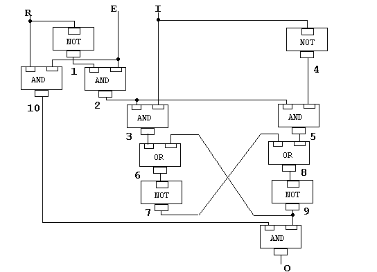
Memory Circuits
A single memory "bit" must have the ability
- to have a data value of either 0 or 1 "written" to it,
- to retain that value after the "write" request is done, and
- to return that retained value at a later time in response to a "read" request.
As another way of thinking about it:
- Sometimes the memory bit is Enabled (to be read from / written to); other times it is in a
"passive" remembering state
- When enabled, a signal must indicate if we are trying to Read from it (the alternative being, write
to it)
- If we are writing to it, an Input data value (0/1) must be provided
- If we are reading from it, an Output path must be provided

Of course, to be very useful, we need many (millions) of these memory bits. A "Selector" circuit
is then required to permit us to access a particular bit (or collection of bits) based on an input
"address".


